
Practical autonomy for the modern jobsite
For my Mechanical Engineering Fourth-Year Design Project at the University of Waterloo, three colleagues and I created Loadrunner: The automated material mover for the construction industry.

What is Loadrunner?
The idea for Loadrunner goes back to working a landscaping job in highschool. Being some of the youngest guys on the crew, we often got stuck with mindless grunt work— moving dirt, gravel, and mulch in wheelbarrows from backyards to frontyards, 8 hours a day, 5 days a week. This was repetitive, mindless, and put a real toll on my body. We thought there had to be a better way.
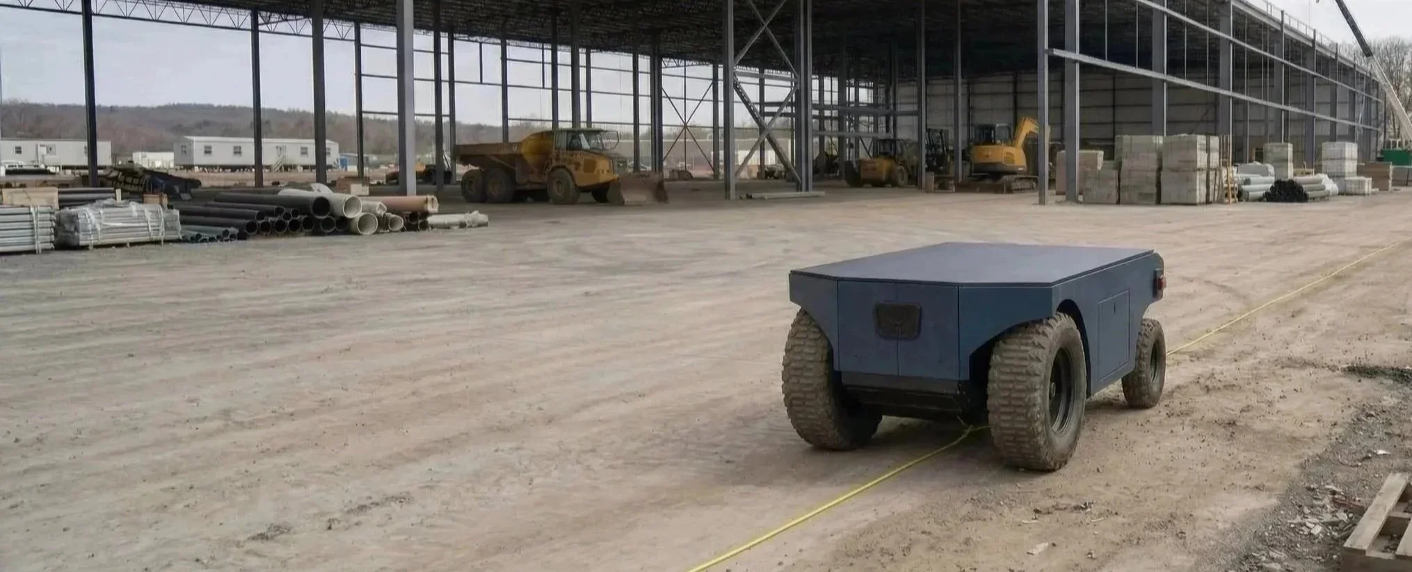
Designed for tight jobsites where skid steers and dump trucks can’t go, LoadRunner autonomously hauls up to 1000lbs of material along a set path with zero operator input. By replacing manual wheelbarrow labour, LoadRunner improves safety and productivity on residential and commercial sites.
Loadrunner delivers reliable, repeatable material transport so that crews can focus on skilled work, not the load.
Custom Designed Inductive Guidance
For construction automation to catch on it needs to just work.
Computer vision is complex, expensive, and fragile. One rogue shovel hitting a LiDAR module means a multi-thousand dollar repair.
When moving dirt through a 6 foot wide sideyard, GPS localization is disrupted.
By laying down a small, reusable guidewire running a low power AC signal the robot always knows exactly where it is and where it needs to go.
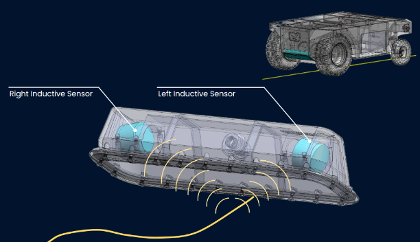
No app needed. No fragile components. No predictive AI. Virtually zero onboard compute required.
Robust analog signal processing. Low BOM cost. Throw down a guidewire and watch it just work.
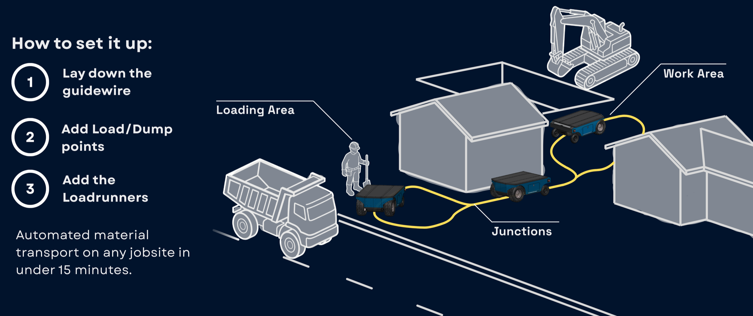
Lay down the guidewire, add stop/go beacons…
…add the Loadrunners to the track, and press start.
Now Loadrunner runs autonomously with an 8 hour battery life fully loaded.
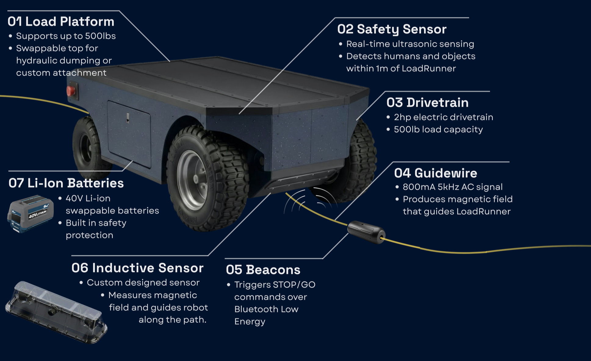
System Overview
Product Design
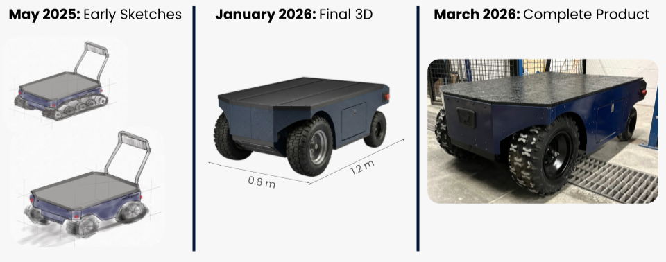
I designed all the major mechanical components of Loadrunner with a primary focus on the frame.
Entirely fabricated from 1/16in mild steel.
Entire frame fits on a $100USD sheet, meaning raw material cost is extremely low.
Designed to be automatically cut by waterjet or laser (~2hrs per frame)
Precisely formed on a CNC press brake (~4hrs labour)
Total cost of the one-off prototype frame was ~$450 USD in material and labour at an external shop.
Final assembly by one person in ~4hrs.
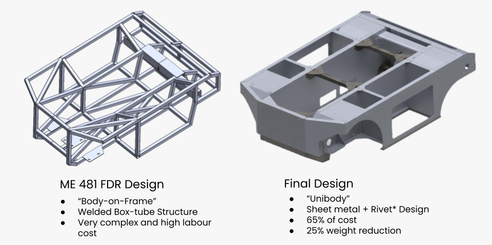
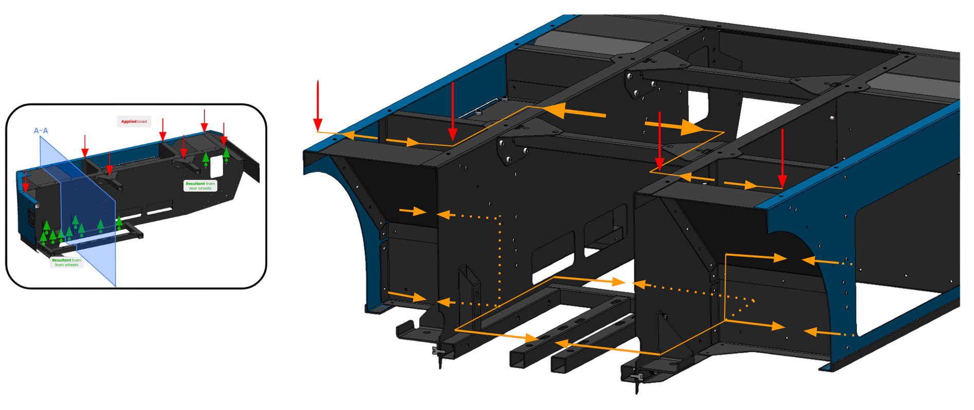
Moving to a unibody frame, the analysis required to validate the strength of the structure becomes exponentially more complicated. Instead of a simple node-member FEA model in ANSYS, this becomes a very compex multi-component model.
Ultimately, I decided that an FEA model would ultimately not inform enough engineering decisions to be worth the time. Instead, as I designed the frame I constantly evaluated the loadpaths ensuring thin sheet metal members would not be in compression and at risk of buckling. By boxing out the sections with bent sheet metal, I was able to create an extremely stiff frame.
While it hasn’t been fully stress tested, we have loaded it up to 800lbs with no noticable yielding or deformation.
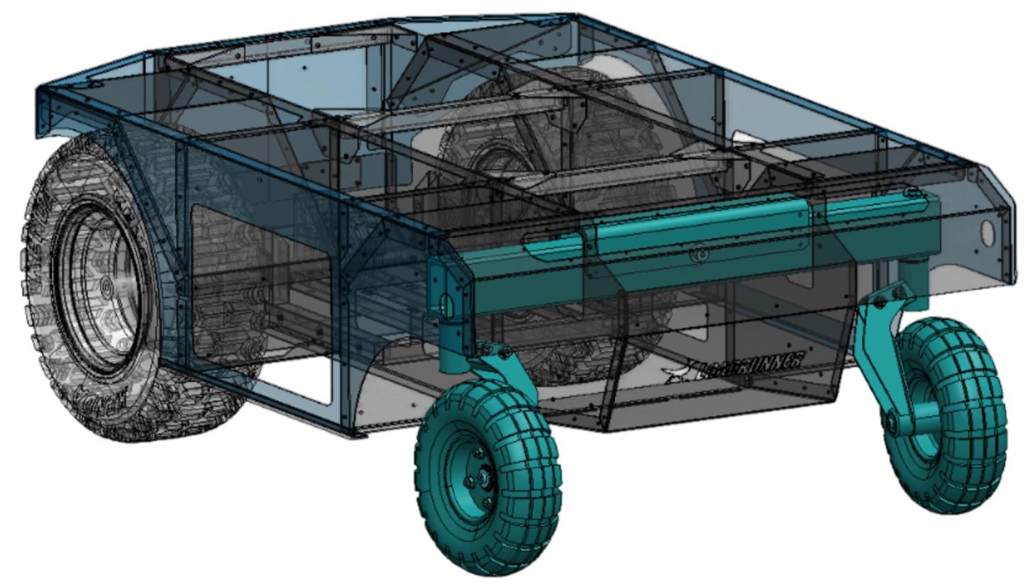
Custom Trailing Castor Design
This was one of the more challenging mechanical aspects to get right on Loadrunner. The trailing castors rotate about a vertical axis and are designed to self center as the robot turns.
The castors are on a central rocker beam that rotates to maintain castor ground contact when moving over varied terrain.
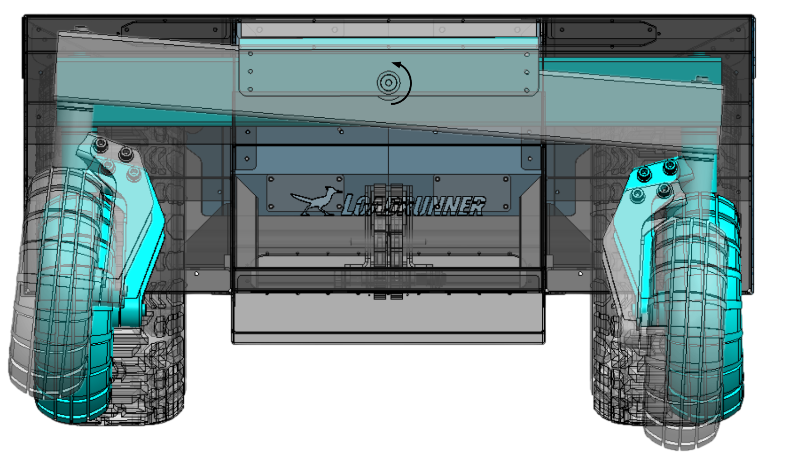
Looking at the turning physics of the robot, Loadrunner turns using front differential drive about an instantaneous center of rotation (ICR). For turning to be smooth, the castors must align themselves tangent to the turn radius.
If a castor fails to self align, it begins to drag on the ground and creates a large moment about the ICR (drag force x R). This moment completely disrupts the plant on the control loop and in the worst case, this causes the robot to veer off track.
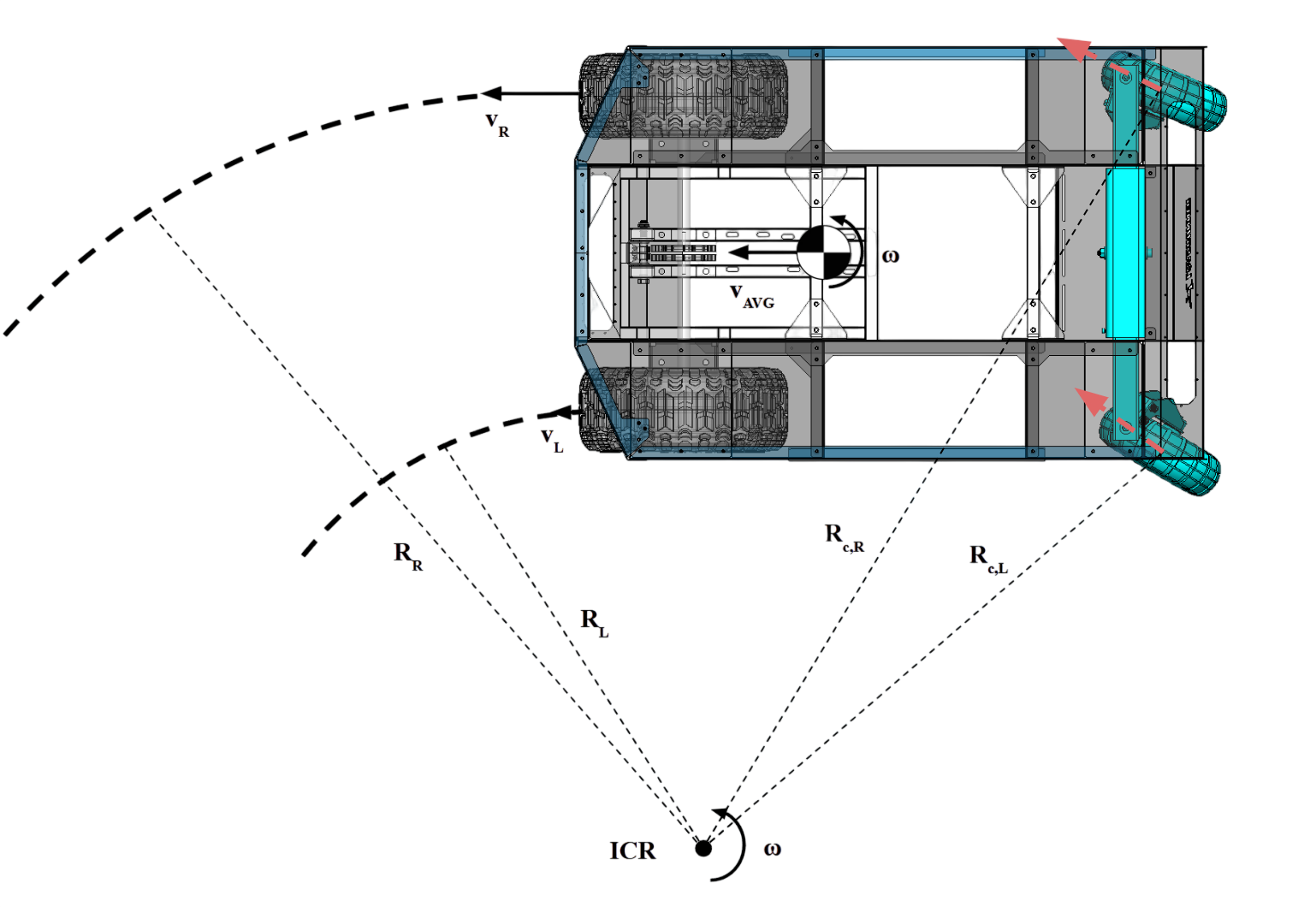
So getting the castor self correction correct was very important. Having a caster offset of roughly 30% of the wheel radius was critical for reliable self centering. Any less and the castor would not self correct; any more and the strength of the caster would be difficult to design for.
Initially I used oil embedded thrust bushings for the castor to improve cost and complexity over ball/needle bearings, but with a full payload, the swivel friction was too high causing turning inconsitency. I had to switch to thrust needle bearings to have consistent self centering.
In hindsight, tapered roller bearings would be the best choice to minimize friction both radially and axially.
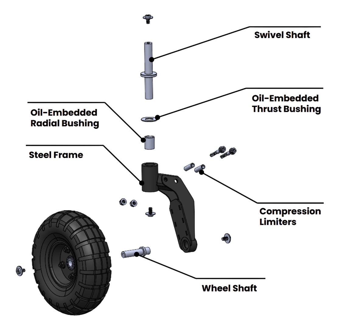
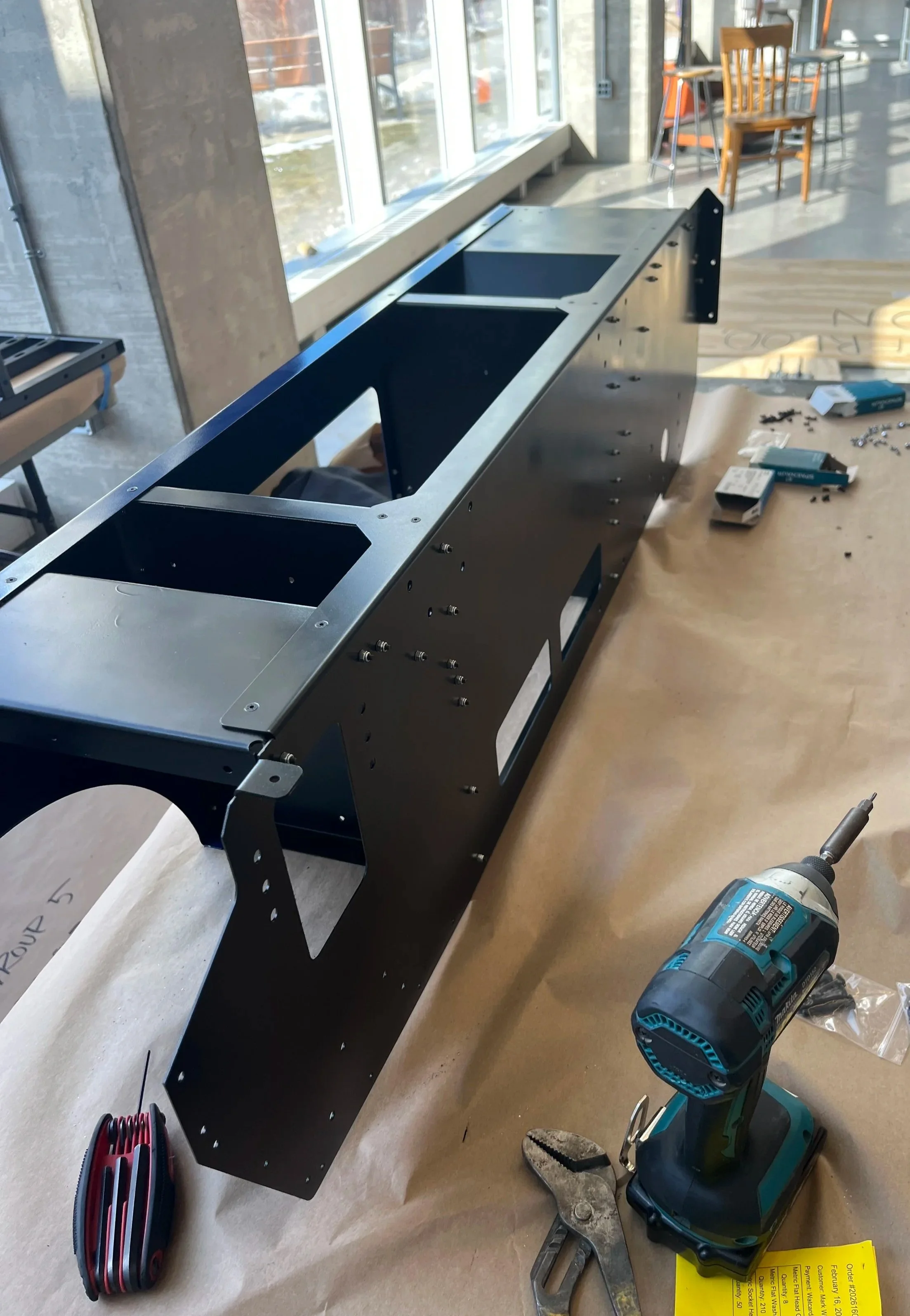
I split the steel frame into two components separated by a bolted joint. This allowed for adjustability of the camber and position of the castor wheels.
While this was useful for adjustability, in practice the M8 bolted joint tended to shift when going over drops and rough terrain.
A fully welded structure would have worked better.
Additionally having a single sided frame for this castor made validating the strength a challenge, but it looks pretty cool :)
Build Execution
After the sheet metal components arrived, I painted and assembled the panels. M3 button head fasteners were chosen over rivets for the prototype to have the ability to easily disassemble and swap components.
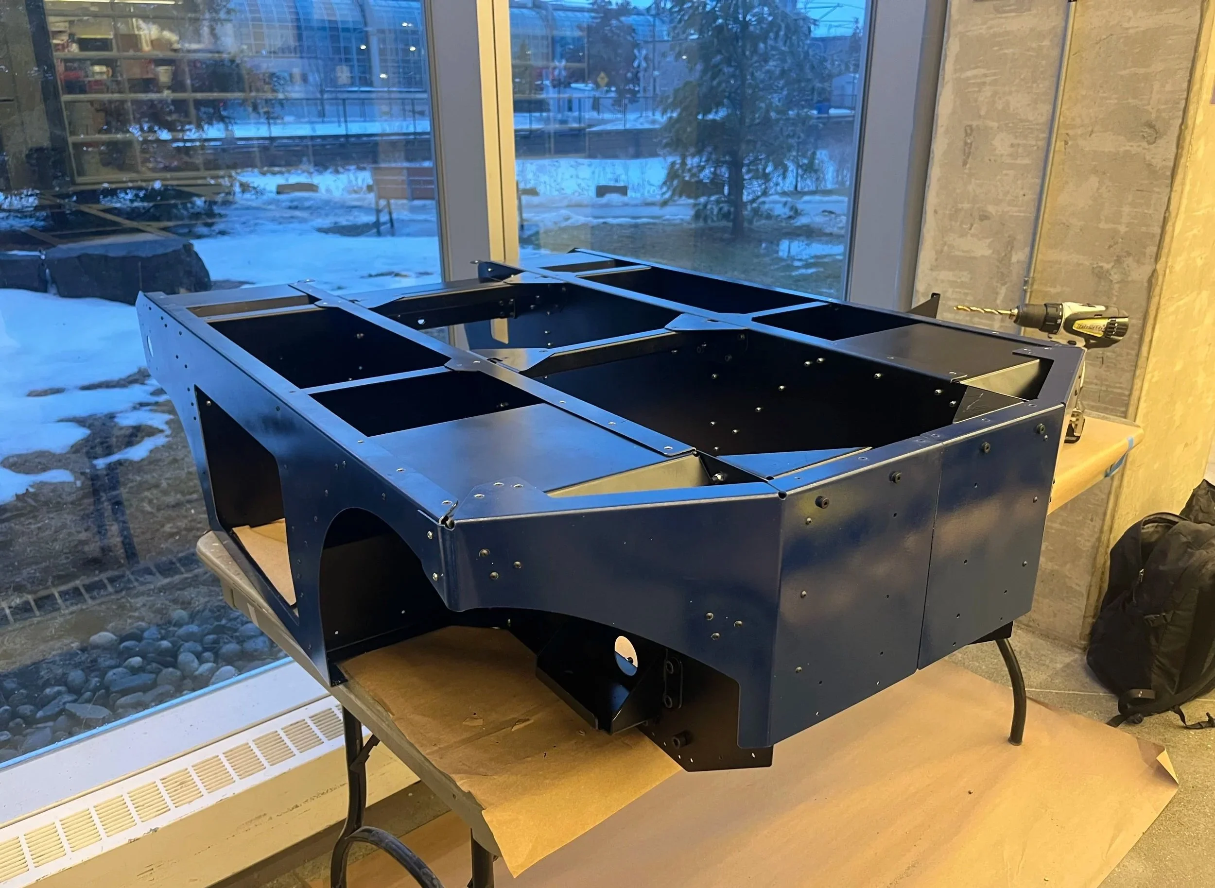
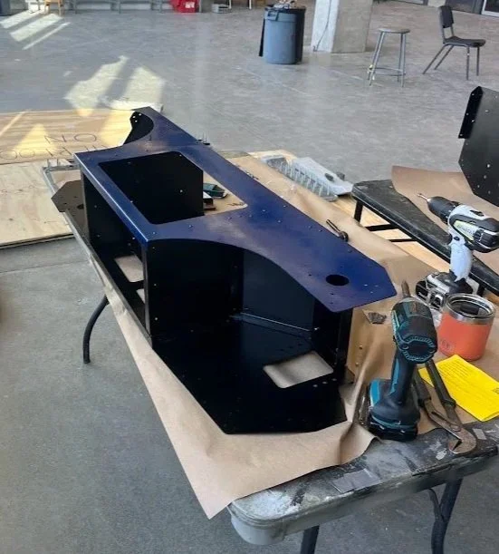
Even though this was just a prototype, I still paid attention to the little details.
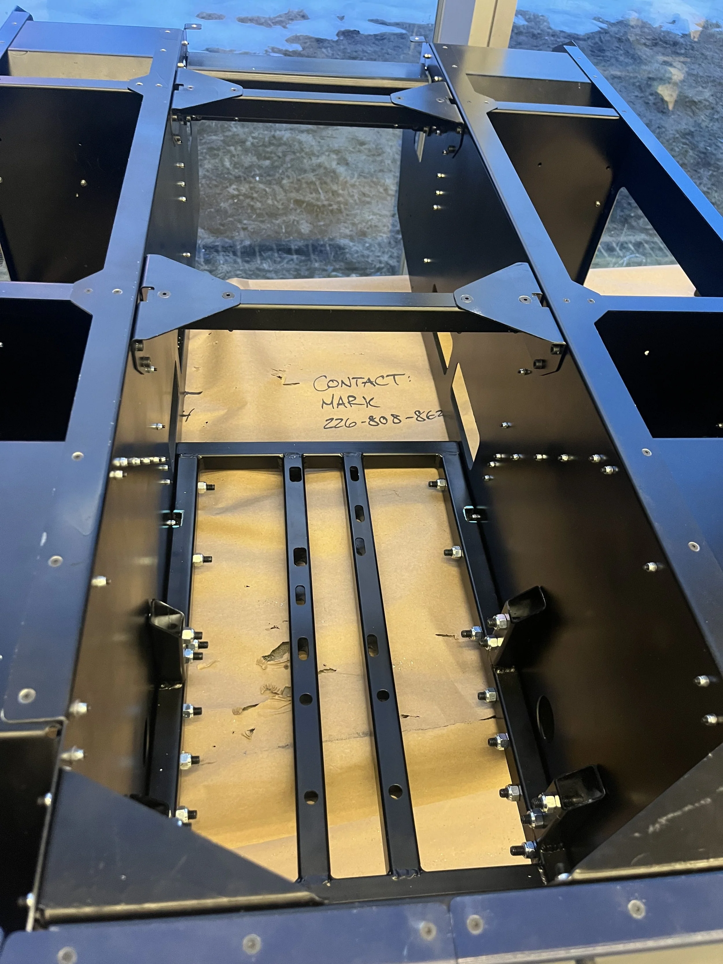
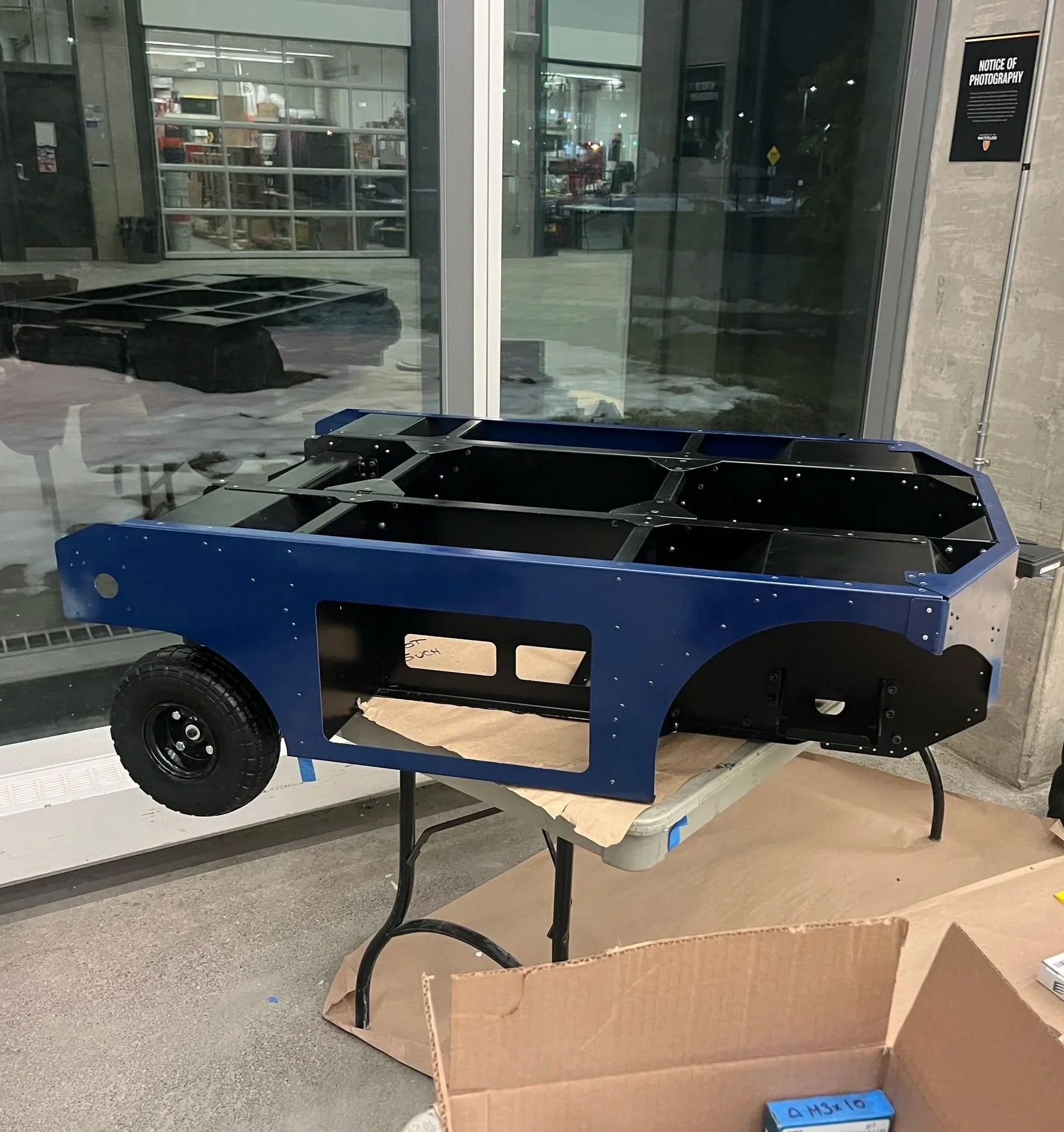
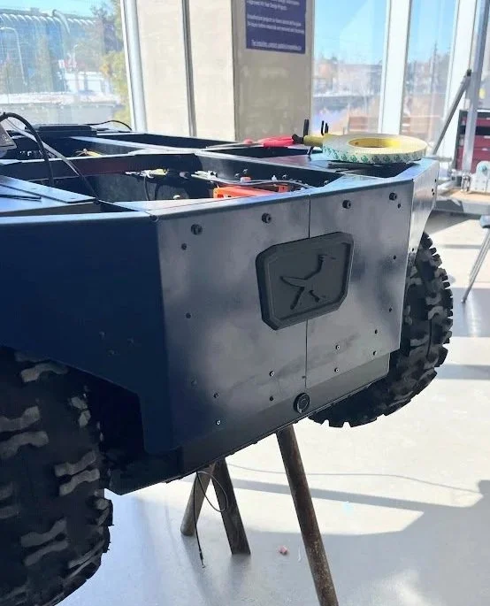
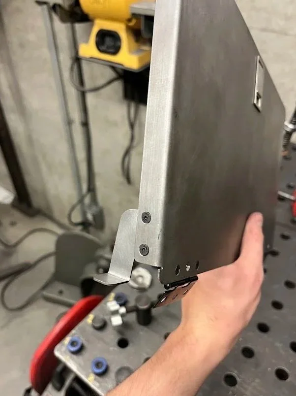
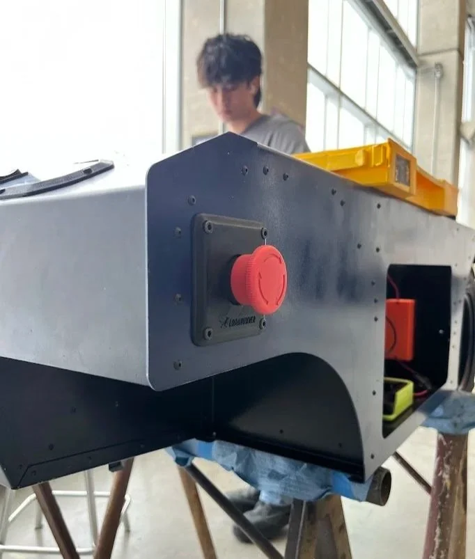
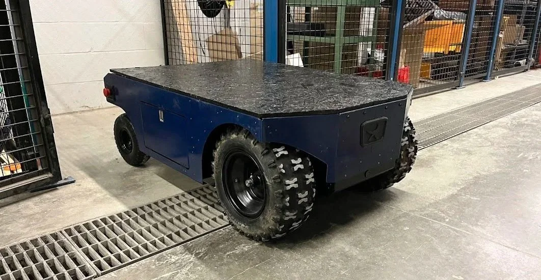
This all cumulated in a fully functional prototype:
Control Theory
A big challenge with this project was the control theory. A big architecture decision was FWD with trailing castors vs. RWD with leading castors. I knew that the RWD setup would lead to a more stable control loop, but the leading castors would have trouble going over obstacles. The FWD setup would be able to handle much more terrain (simply due to a larger wheel diameter), but would lead to a less stable control loop.
Another way of thinking about this is pushing a shopping cart forwards with front castors and fixed back wheels— it is easy to maneuver. If you try pushing a shopping cart backwards with the fixed wheels at the front, you will find it’s much more difficult to maneuver and will feel less stable. However, it’s still doable if you are careful.
For the FWD version, I wanted to understand the controls and physics by simulating the model before building.
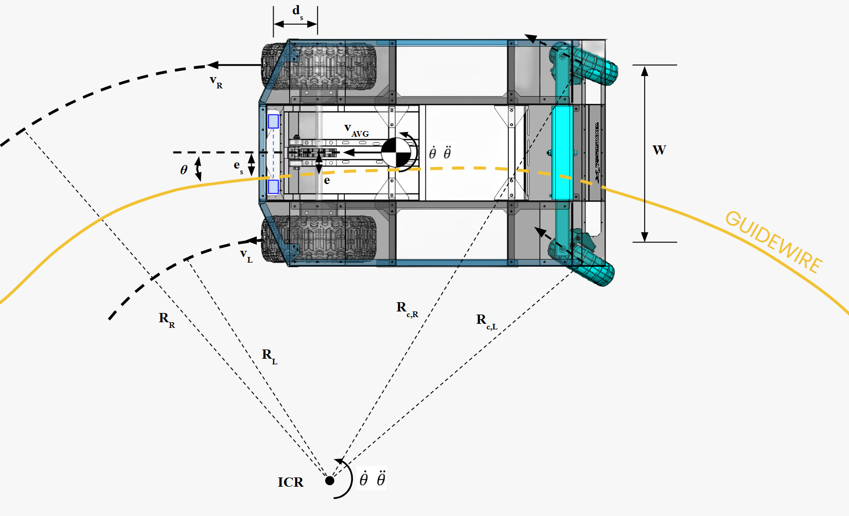
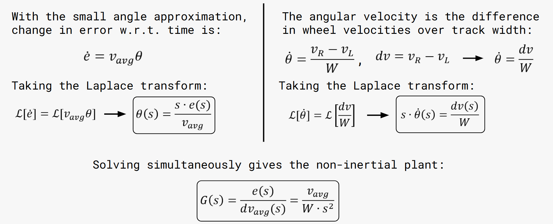
The position of the robot is decribed by the angle between the robot central axis and the track and the error distance (e) to the track.
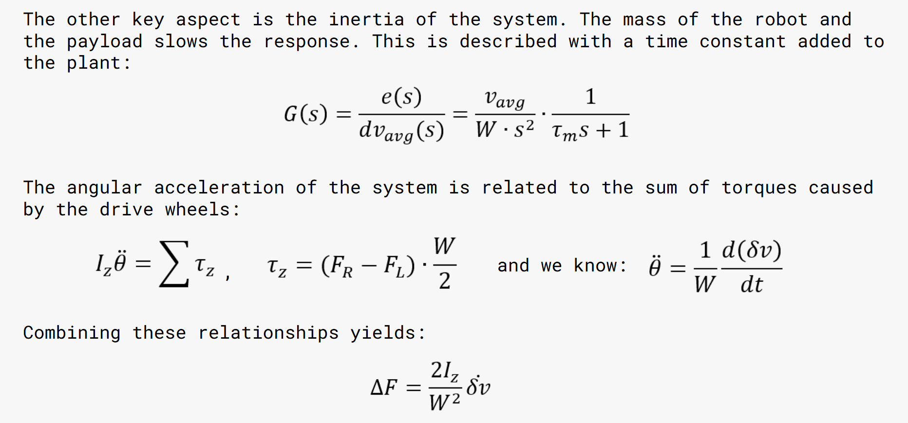
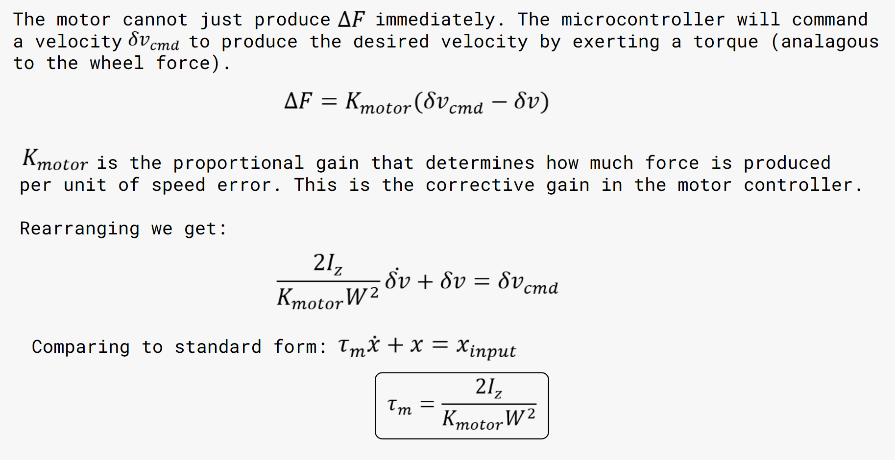
The behaviour of the robot (how it turns) is decribed with the velocities of each wheel which relates to the average velocity and the angular velocity/acceleration of the vehicle.
Plant Function: